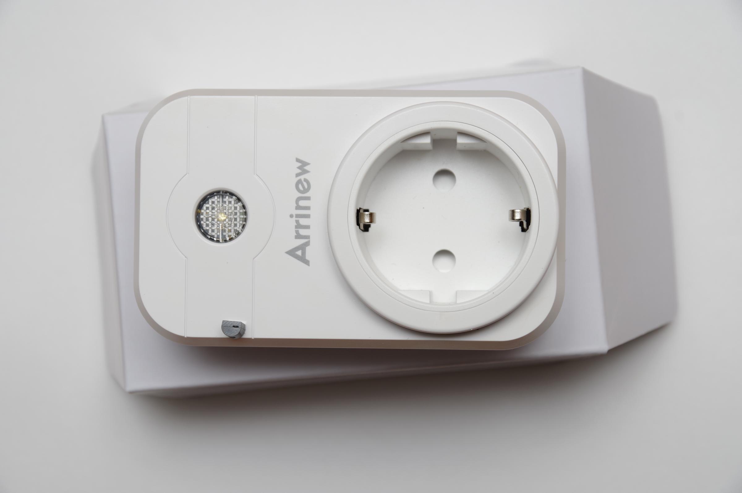
Wer seine Wohnung automatisiert, kommt ja früher oder später nicht an den preiswerten WLAN-Steckdosen vorbei mit denen man ferngesteuert Verbraucher ein- und ausschalten kann. Für mein (momentan) auf HomeAssistant basierendes System habe ich zum Schalten der Pflanzenlampen geeignete Steckdosen gesucht, die sich mit einer selbstgeschriebenen Firmware bespielen lassen (oder einem der freien “Betriebssysteme” dafür). Alle kaufbaren WLAN-Steckdosen verbinden sich normalerweise mit der Cloud (also einem Server) ihres Herstellers. Wenn man z.B. eine Lampe mit dieser Steckdose übers Handy einschalten möchte, kontaktiert die Handy-App den Hersteller-Server und übermittelt diesen den Schaltbefehl. die WLAN-Steckdose ist ständig mit ihrem Hersteller -Server verbunden und bekommt dann von diesem den neuen Schaltzustand mitgeteilt. Das ist in der Einrichtung sehr einfach, weil man nichts weiter konfigurieren muss, aber dennoch eine äußerst dumme Idee. Zum einen geht nun wirklich niemanden etwas an, was ich gerade ein- und ausschalten will, zum anderen muss damit die Sache funktioniert, meine Internetverbindung stehen und der Herstellerserver verfügbar sein. Bei beidem hat man erfahrungsgemäß so seine Hänger. Glücklicherweise basieren die meisten WLAN-Steckdosen auf den gleichen Chip und man kann diesen selbst programmieren, so dass diese nie ihren Herstellerserver kontaktieren (brauchen). Bei Amazon bin ich auf ein preiswertes Zweierset (unter 20,-) in guter mechanischer Qualität gestoßen, dass unter dem Namen Arrinew vertrieben wird. Die gleiche Dosen sind vermutlich unter mehreren Handelsnamen verfügbar. Eindeutiger ist die Beschriftung auf der internen Leiterplatte: Model: SWA1, 101-SWA1351-361
corinnakopf leaked
Die Dosen haben wirkliche eine sehr gute mechanische Qualität, auch die beiden Elektronikboards im Inneren machen den Eindruck eines wertigen Gerätes. Unglaublich, was für 10,- verkauft wird.
Wer jetzt hier weiterliest, sollte wissen was ein ESP8266 ist und schon mal was von MQTT gehört haben. (oder ansonsten nur wissen wollen, was der Ralf so treibt 😉 )
Ziel der ganzen Aktion ist es, die Firmware der Dose mit einer eigenen zu ersetzen und damit die Cloud des Herstellers loszuwerden. Betreibt man seinen eigenen Heimautomation Server (z.B. auf einem sehr billigen und stromsparenden Raspi), ist man auch ohne eine Fremdcloudanbindung für alles gerüstet. Für jegliche selbstprogrammierte Firmware in diesem Bereich bietet sich eine Anbindung über das universelle MQTT-Protokoll an, dass man in alle (freie) Heimautomation-Systeme einbinden kann. Man muss dazu also die Firmware der Steckdose durch eine andere ersetzen. Es gibt hierfür eine Reihe fertige universelle Systeme (Takoma, EasyESP …) man kann aber mit der Arduino-Entwicklungsumgebung auch eine eigene Firmware erstellen, was schwieriger klingt, als es wirklich ist. Um nicht mit den fertigen universellen Systemen kämpfen zu müssen und die Interna besser zu verstehen, habe ich mich für den zweiten Weg entschieden, zumal hier bereits alles soweit vorbereitet ist.

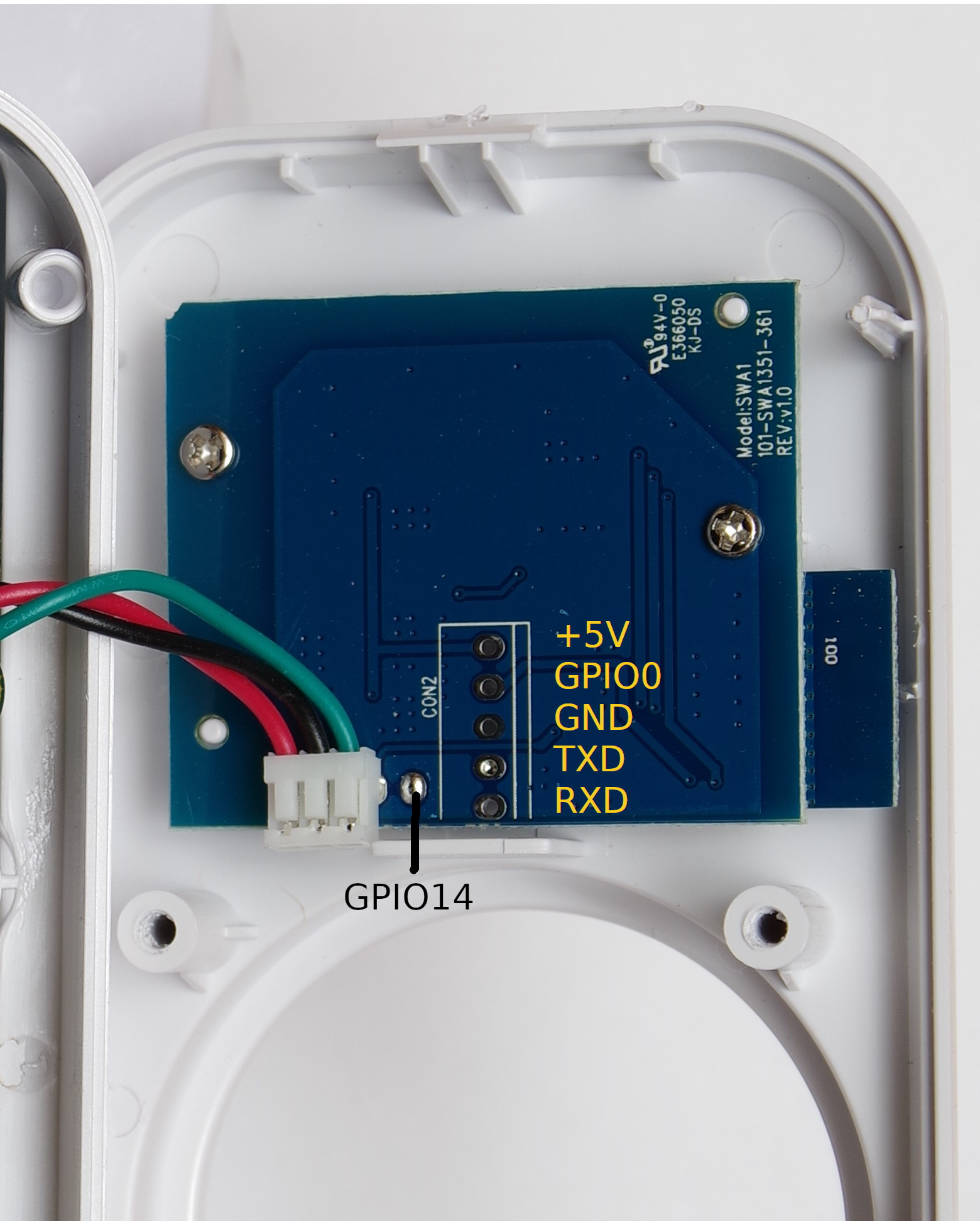
Die Arrinew-Dosen sind für die Programmierung insoweit vorgerüstet, dass die Programmierkontakte gut herausgeführt sind. Aber leider sind sie nicht beschriftet. Da fangen die Probleme an, der ESP-Chip ist mit einem Blechdeckelchen gekapselt und man kann so die Pins nicht nachverfolgen. Ich bin aber über den Leiterplattenaufdruck hier fündig geworden, da hat jemand sich schon einmal die Mühe gemacht und alles herausbekommen.

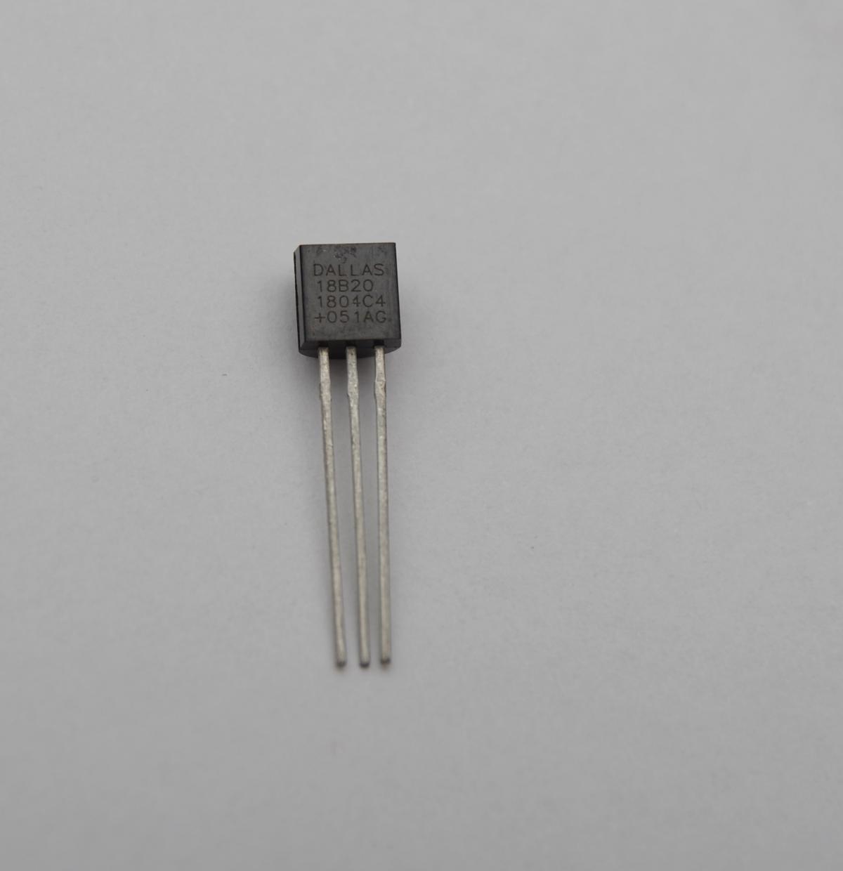
Interessant ist zudem, dass an einem unbestückten Pin von CON1 ein freier GPIO anliegt (GPIO-14). Das schreit gerade zu danach, verwendet zu werden. Da man nie genug Temperatursensoren im Haus verteilt haben kann, habe ich also hier einen digitalen One-Wire Temperatursensor DS18B20 angeschlossen. Damit beschäftigen wir uns aber im zweiten Teil.
Das Programm ist auch von Matt geklaut und etwas erweitert worden und sieht dann so aus:
// Flash mode: DOUT
// Flash Frequency: 40MHz
// Flash Size: 1MB (512kB SPIFFS)
// Reset method: None
// Crystal Frequency: 26MHz
// CPU frequency: 160MHz
// Upload speed: 921600

// Button: GPIO13
// Blue LED: GPIO4
// Red LED + Relay: GPIO5
// Extra Pin: GPIO14, used foor one-wire temperaure sensor

#include <ESP8266WiFiMulti.h>
#include <ArduinoOTA.h>
#include <PubSubClient.h>
#include <DebouncedInput.h>
#include <OneWire.h>
#include <DallasTemperature.h>


ESP8266WiFiMulti wifiMulti;
WiFiClient espClient;
PubSubClient client(espClient);

#define ONE_WIRE_BUS 14  // DS18B20 pin
OneWire oneWire(ONE_WIRE_BUS);
DallasTemperature DS18B20(&oneWire);


bool powerState = false;
unsigned long previousMillis=0;

#define NAME "name for OTA"
#define OTAPW "password for OTA updates"
#define BROKERUSER "MQTT broker user"
#define BROKERPASS "MQTT broker password"

// define here your MQTT topics
#define SUBTOPIC "/powerplugs/switch02/command"
#define PUBTOPIC "/powerplugs/switch02/status"
#define TEMPTOPIC "/powerplugs/switch02/temp"

#define POWERPIN 5
#define BUTTONPIN 13
#define LEDPIN 4
#define TEMP_INTERVALL 10000  // temperature is measured every 10s

DebouncedInput button(BUTTONPIN, 10, true);

void callback(char *topic, byte *payload, unsigned int length) {
    if (!strcmp(topic, SUBTOPIC)) {
        if (!strncmp((char *)payload, "on", length)) {
            digitalWrite(POWERPIN, HIGH);
            powerState = true;
            client.publish(PUBTOPIC, "on", true);
        } else if (!strncmp((char *)payload, "off", length)) {
            digitalWrite(POWERPIN, LOW);
            powerState = false;
            client.publish(PUBTOPIC, "off", true);
        }
    }
}

void setup() {
    button.begin();

    WiFi.mode(WIFI_STA);

    pinMode(POWERPIN, OUTPUT);
    pinMode(LEDPIN, OUTPUT);
    digitalWrite(POWERPIN, LOW);
    digitalWrite(LEDPIN, LOW);

    client.setServer("IP of your MQTT broker", 1883);
    client.setCallback(callback);

    // Add more of these for access to more APs.
    wifiMulti.addAP("WiFi name", "WiFi password");

    ArduinoOTA.setHostname(NAME);
    ArduinoOTA.setPassword(OTAPW);
    ArduinoOTA.begin();

    DS18B20.begin();
}

void loop()
{
    static uint32_t ts = millis();
    ArduinoOTA.handle();
    client.loop();

    if (wifiMulti.run() != WL_CONNECTED) {
        delay(100);
    } else {
        if (!client.connected()) {
            delay(100);
            if (client.connect(NAME, BROKERUSER, BROKERPASS)) {
                client.subscribe(SUBTOPIC);
            }
        } else {
            if (millis() - ts >= 5000) {
                ts = millis();
                client.publish(PUBTOPIC, powerState ? "on" : "off", true);
            }
        }
    }

    if (button.changedTo(LOW)) {
        powerState = !powerState;
        digitalWrite(POWERPIN, powerState);
        if (client.connected()) {
            client.publish(PUBTOPIC, powerState ? "on" : "off", true);
        }
    }

    digitalWrite(LEDPIN, !client.connected());

  unsigned long currentMillis = millis();

  // if you don't use the temperature sensor, comment out the following block
  if(client.connected() && (currentMillis - previousMillis) > TEMP_INTERVALL){
    char h[20];
    float temp;
    DS18B20.requestTemperatures();
    temp = DS18B20.getTempCByIndex(0);
    sprintf(h,"%.1f",temp);
    client.publish(TEMPTOPIC,h,true);
    previousMillis=currentMillis;
  }

}
Compilieren und programmieren kann man das mit der Arduino-IDE. Im Netz gibt es dazu viele Anleitungen. Dank der verwendeten Bibliotheken ist das Ganze recht kurz und übersichtlich.
Man muss natürlich vorher den Code noch individualisieren (WiFi Zugangsdaten, MQTT-Server und -topics).
Folgende Sachen sind mir aufgefallen:
- Es gibt eine blaue und eine rote LED, die man durch den transparenten Taster sieht. Die blaue leuchtet, wenn die Verbindung zum MQTT-Broker steht (WLAN funktionier und der MQTT-Broker läuft und ist erreichbar). Das ist nebenbei auch ein guter Indikator, dass die eigene Homeautomation läuft. Die andere LED ist rot und leuchtet, wenn die Dose eingeschaltet ist.
- Die Arduino-Netzwerkbibliothek hat offensichtlich Probleme, lokale IP-Namen aus der Fritzbox aufzulösen. Ich musste die IP-Adresse des MQTT-Brokers eintragen.
- Der WiFi-Name ist case sensitiv
- Die Dose braucht als payload zum Schalten “on” und “off”, Das kann man aber auch im Quellcode ändern.